Lt1 reverse flow cooling system diagram Reverse flow cooling, worth it? Flow diagram cooling reverse lt1 system coolant chevy direction engines pontiac 1960 later which car easily come over not
Lt1 Reverse Flow Cooling System Diagram
Cooling system engine diagram car coolant prestone equipment heavy truck imagine release so systems duty hd maintain vehicle maintenance components Radiator cooling system routing help! Cooling system l gavin fleet care l bedford vehicle cooling services
Thermostat toyota coolant 22r samarins mechanic symptoms parts 22re
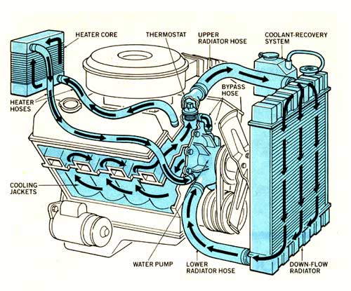
Reverse flow cooling system?Basic engine cooling system: how to cool an engine in 2 ways Intake restrictor manifold grumpysperformance coolantWater restrictor in intake manifold.
Lt1 diagram flow engine reverse water pump cooling system hose gm chevy z28 wire routing plug heads camaro gen technologyLt1 reverse flow cooling system diagram Coolant radiatorLt1 cooling reverse system flow diagram corvette.

Toyota 22r engine coolant diagram
Lt1 reverse flow cooling system diagramCoolant diagram tank radiator system overflow flow cooling ls ls1 expansion routing swirl swap steam lsx heating ls1tech ports camaro Reverse flow cooling system water wireHow to maintain your hd engine coolant system.
Cooling engine diesel system coolant block transmission engineers edge gif thermostat llc copyright 2000 2021 powerLt1 cooling routing heater hoses camaroz28 Lt1 reverse flow cooling system diagramCooling system diesel engine.

Lt1 flow corvette camaroz28 moparts ubbthreads routing
Flow diagram lt1 cooling system reverseLt1 reverse flow cooling system diagram Flow system cooling diagram reverse lt1Lt1 reverse flow cooling system diagram.
.


Lt1 Reverse Flow Cooling System Diagram - Wiring Diagram Pictures

Basic Engine Cooling System: How to cool an engine in 2 ways - Basic

Cooling System l Gavin Fleet Care l Bedford vehicle cooling services
water restrictor in intake manifold - Corvette Forum : DigitalCorvettes

Toyota 22r Engine Coolant Diagram | Online Wiring Diagram

How to maintain your HD engine coolant system - Truck News

Cooling System Diesel Engine

Lt1 Reverse Flow Cooling System Diagram - Wiring Diagram Pictures

Lt1 Reverse Flow Cooling System Diagram